Author Archives: ken

Integrator Product Page

Attention! Please Read!

If you are interested in purchasing integrators or integrator components, you can leave me a message via the contact page. However, I have recently found that many of my replies are being rejected by spam filters. So if you have left me a message, you can generally expect a reply within 24 hours. If you do not, it is likely that my reply has been blocked and you should please have a look in your junk or spam filtered folder in your email client. I use email because it suits my international, niche market and e-commerce tools are too limited or expensive for my sales. Unfortunately, email has become a kind of wild west with no real guarantees of smooth delivery but it is still the best way for me.

The V5.9 Integrator is no longer available. I can only supply the very last few bare PCB’s and PCB’s assembled with switches. The reason is, a new integrator version 6.0 is in development, and I need to concentrate my time and effort on the new device. It is in the circuit design and PCB layout stage now, and units should be available later this year. The time frame has been pushed back again because I want to do a good job on it, and I am not building any more or ordering parts because it distracts me from that task. So please bear with me. I can not accept any more requests to be on a waiting list because it will become too hard to manage and too hard to notify everyone when the new device is ready.

This device contains a high impedance preamplifier and signal integration function, for analyzing electric guitar pickups. It has gone through several stages of prototyping and design improvement. The latest update is an acrylic front panel. It looks really cool in the dark, although you probably won’t be testing pickups in the dark!

As a specialized test instrument, the market for it is relatively small, so a challenge was met to offer a product that is both economical and robustly constructed, and also can be made by an experimenter, following the free and completely open online documentation and design files, found here:

https://github.com/KenWillmott/integrator/wiki

In the spirit of open source, I have made it possible for any customer to choose whether they wish to make their own, or purchase component parts or complete units from me. I offer a variety of kit options, from only the PCB, to a parts kit and assembled PCB, all the way to assembled, tested and calibrated unit.

Also because of the limited market, it is not economical or feasible for me to set up an online store where you can simply shop and check out your purchases. The global distribution of my customers also means that optimum shipping varies considerably depending on which country I’m sending to. Consequently, I operate by communicating with each individual customer via email, to choose the right kit or parts and to choose the best payment and shipping options.

Many people have already purchased and/or built some previous version of the Integrator. Any of those do work perfectly well, but if any previous customer wishes to upgrade to the new product, please contact me with the details of the their unit, for an assessment of upgrade options.

Price List:

  • PCB only: US$8
  • PCB assembled with parts (including IC, switches not soldered): US$45

Guitar Pickup Measurement Revisited

It has been 5 years since my first experiments with guitar pickup measurements began. I discovered several people that had performed experiments and published them on the internet. But why would I want to measure pickups? It began with a guitar. I had always been a Gibson player, but tried a Fender Telecaster one day and liked it so much I bought it. However, I was queasy about the non-humbucking pickups that it had. So I set about to replace them.

I expected to find some concrete wisdom online, but found nothing that satisfied my technical appetite. So I just asked the guy at the counter in the music store. He suggested a Seymour Duncan SH-2 Jazz pickup for the neck. I had already been to the Seymour Duncan website and found the “sound system” ratings that they publish – these are bar graphs showing bass, midrange and treble levels. I couldn’t make much sense of those so I just followed the guy’s advice. It did sound good, but it left me wondering why.

Later, I found myself in China with a bit of spare time on my hands. I began to track down some interesting research, such as the work of Helmuth Lemme, http://www.buildyourguitar.com/resources/lemme/

I wondered, “could I build a pickup measurement system using simple everyday parts instead of the lab instruments that many of the published researchers were using?”. So on the magnificent window facing wooden desk set of my study at the school, I built this prototype:

circuit layout
This is the whole test circuit, looking ugly now because it is built in air! At the top is the battery powered integrator. Magnetic probe is placed on the pickup.

It did not perform very well, but it did work. In the meanwhile, I found and began to collaborate with other people that had similar interests. That led to improvement of the same circuit. I made the first PCB, the V5.7, and built some systems which shipped to a few interested people all over the globe. This previous article explains more: https://kenwillmott.com/blog/archives/152

Gradually, the experience with the V5.7 produced a list of needed improvements. That kick started the development of the same circuit as a more manufacturable and versatile product. Fast forward about 2 years to 2019, and it is here:

V5.8 integrator top view
V5.8 integrator PCB and internal wiring
V5.8 PCB with standard components

So, what does it measure, and how could you use those measurements? The pickup sits between the strings and the amplifier, so it is a kind of gateway through which the sound has to pass. It’s also an electrical component, so it has a thing called an “impedance” – more on that later. As a gateway, it is not transparent, but has different degrees of response at different audio frequencies – together referred to as a “response”. This device measures the response, which can be recorded, studied, and compared with the responses of other pickups.

If you feed a constant, unvarying test signal to a pickup (instead of the vibration of a string), and plot the output signal at all the relevant audio frequencies, you get a “Bode plot”, which is just a graph of amplitude vs. frequency. A small test coil can provide a test signal, and an appropriate PC application can easily generate a test chart, such as this one:

Sample humbucker Bode plot – “raw” unloaded plot shown in white, load applied to simulate actual guitar circuit performance shown in green

It’s worth discussing a few common response features at this point – nearly all pickups share them because they all effectively operate the same way. Below 1 kHz, you can see that the response is “flat” – the amplitude does not vary with frequency (one implication of that, is that the term “bass response” of pickups has no useful technical meaning). Then, at some frequency which is about 2.4 kHz in this example, there is usually a peak (in this case +1 dB louder than the reference level below 1 kHz). Above that frequency, the signal diminishes rapidly and never returns.

How would this impact the perceived sound? Well, in the flat portion, all pickups sound the same. That is because the pickups are passing the string vibration identically and uniformly. The intensity (here, the height) of the peak imparts a bell-like resonance which may or may not be audible depending on the amplitude of the peak. The “cutoff” or drop in signal always follows the peak, so the frequency of the peak also determines the frequency at which the fall-off occurs. The fall-off of higher frequencies mainly influences the perception of treble – the “brightness” or “dullness” of the sound. Note that such perceptions are value independent – personal preference can translate “bright” into “shrill” and “dull” into “smooth” or some other adjective.

The overall similarity of the response of different pickups is due to the identical electrical model that they all share. Thus, disregarding small differences, nearly every pickup can be distinguished electrically by its resonant frequency, height of resonant peak or “Q”, and sensitivity to string vibration or “output”. There are other differences due to magnetic field geometry (“aperture”), non-linear magnetic field strength imparting harmonic content, and harmonic effects on the string from the constant force of the applied magnetic field. I am only listing the proven ones. However since these 3 factors will be similar between any two of the same general type of pickup, the response itself is a predominant and reliable indication of the sound.

There are many applications for the measurements. You can predict tone approximately, compare altogether different designs and evaluate the effects of different internal components such as magnets, compare different pickups of the same production run, detect defects like internal shorts that are not evident in a simple resistance measurement. With access to an online database, you can select pickups that are similar to ones that you already like, disprove specious claims about pickups, test new designs and so on. I have seen photos of similar devices taken on factory tours of some major pickup manufacturers, so they use them even if they don’t talk about it – they like to project an image more tailored to “connoisseurs” of tone, more in tune with instrumentalists.

V5.8 integrator on test bench measuring a single coil guitar pickup

The system works in the following way – a test signal is applied to a small coil through a resistor. This creates a magnetic test field that substitutes for a vibrating string. The coil is placed adjacent to the pickup, and a plot is created. There is a small problem – an alternating magnetic field generates a voltage signal that is the mathematical derivative of the field. This is predicted by Faraday’s Law. It is not part of the response of the pickup “as a filter”. So it is necessary to apply the inverse of differentiation, which is mathematical integration. The V5.x devices contain an “integrator” circuit to perform this function, as well as a highly sensitive preamplifier that prevents the circuit from itself affecting the pickup that it is connected to.

There is another way to measure pickups, by treating it as a device with no magnetic input and simply measuring the complex impedance at all frequencies. This is a perfectly acceptable method, but does not yield response curves directly, thus requires specialized software. It has the advantage that response curves for arbitrary loads can be simulated correctly, and that the test hardware can potentially be very simple. However, at this point in time it is under development by a few people who have not yet made it publicly available as a working package. I certainly hope that they do, but my hardware integrator solution works well now with generic PC software available for/with PC audio hardware or hardware oscilloscopes. Also, measurements with a magnetic exciter coil such as in my system, are more accurate than direct impedance measurements when eddy current losses are present between the string and the coil (often true in metal pickup covers).

The V5.8 brings mostly practical improvements to the V5.7 that I developed and distributed PCB’s for several years ago. The assembly has been simplified by locating all the switches on the PCB. A variable capacitor makes calibration easy. Bulk procurement has enabled me to reduce the parts cost and so I can offer assembled PCB’s at a low cost, and the improved assembly also allows me to construct complete systems at a very reasonable price. As the market for it is not big, I have not constructed an e-commerce site for them. But if you want one, or you want to build one, just contact me and I will work something out with you.

It is an open source project, I have published all the PCB designs, so that anyone can make them. I’ve also provided schematics and parts lists. It can be found here: https://github.com/KenWillmott/integrator

Another in a Continuing Line of LED clocks

The clock collection grows with this double 8×32 LED display version. I actually promised myself I wouldn’t use the LED matrices again, for aesthetic reasons, but I already had two of them extra, and it was a chance to improve my housing construction techniques. Also, it is a leap away from the AVR based hardware platform to the ST Micro STM32F103C8 processor in the form of a Maple Mini. The advantage is that the Maple is smaller, cheaper and faster than a larger Arduino board like the Mega2560, and also has multiple serial ports which is important for interfacing an internet device like the ESP-01, a Bluetooth or a GPS module. The system is made with 2 MAX7219 based matrix displays, and a proto board housing the Maple processor, an RTC module for timekeeping, and an ESP-01 for WiFi access. Functionally, the system goes to an NTP server via WiFi, to get the exact time when power is applied, and every 10 hours after that. It uses that time to set the RTC in case internet is lost. WiFi and other settings are configured from a computer through the USB port that powers it. It understands daylight savings time, and has a database of about 30 global time zones. So once it is set up, it never needs any kind of attention unless WiFi setting have to change.

The housing uses high grade 1×4 pine, which is easy to work with and finish with polyurethane. There are three main aspects that make the box fit the electronics and display effectively. There is a saw cut all around the inside of the front that forms an escutcheon (holder, if you like) for the filter. In the middle of the interior, there is a post that mounts the display on one side and the processor on the other. A sheet of thin plywood covers the back.

No doubt, someone who is experienced in woodwork would suggest improvements in my method. But I don’t have a real wood shop, just a table saw and hand drill. So my method is evolving around those limitations. First I make the shallow saw cut about 5mm from the front for the filter. Then I cut the side, top and bottom pieces from that. It helps to cut slowly, which makes a cleaner cut across the wood grain. I measure and cut the center post and back cover. This leaves gaps where the saw cut meets the edge. I fill these by gluing in wood spacers, which i trim carefully after the glue is dry. The housing pieces are assembled by laying them square on the saw table and drilling for the screws. After assembly, I apply at least two coats of polyurethane from a spray can, with light sanding in between coats. It helps to let the poly dry overnight even though they talk about 2 hour drying time. When I’m happy with the outside, I paint the inside with black craft latex, to eliminate reflections and to minimize what can be seen through the filter. A future upgrade will be to hide the top screws with plug dowels.

I have been asked whether I can develop projects using more off the shelf components, so that other people would have an easier time duplicating them. There are problems in that. I always find weaknesses in the inexpensive hardware that I get, which not everyone has the patience to fix. For example, most low cost MAX7219 displays have an excessive LED current due to a poor bias resistor choice. I think it is because the designers think that people are too dumb to turn up the brightness in software. I chose to do SMD surgery to fix that on these display boards because I loath to run components outside their specified limits. The popular library to drive these displays views each 8×8 module rotated by 90 degrees, so I had to modify the code to change that. I also have found that the ESP-01 modules can be powered down when not in use, yet most hobby circuits don’t bother to do it. So in many cases, hardware and software modifications are required to make a project really useful.

In fact, I have two other clock projects in the works, where I am trying to create something that the average experimenter could duplicate. I am trying to avoid the special mods and things and put together a code base that isn’t also a hodge podge of modified libraries like I often have to use. Mainly here, I’m showing you how to take your clock hardware, and put it in a presentable and pleasing box.

Phantom Powered Guitar Preamp

The idea of putting a preamplifier in a guitar is hardly new. There are many advantages, but a big disadvantage is the requirement for power, which usually means that a battery has to go into the guitar. That means that a space must be found for the battery, it must be replaced when it expires, and has the potential to leak corrosive liquids inside the guitar if left for too long.This circuit avoids those problems by using a common idea from microphone technology, phantom powering. Many microphones obtain power for internal circuits from an ingenious circuit that allows power to be transmitted over audio cables. This system has become a standard, and is provided by most microphone preamplifiers and mixing consoles.

Originally, the power was used to bias condenser microphones, and so the voltage is quite high, 48 volts. Originally, a transformer was used to separate the audio from the supply voltage, but in recent years transistors became available that could do that, and so the “Schoeps circuit” was developed by the engineers at Schoeps Mikrofone to replace it.

The Schoeps circuit has been adapted and modified endlessly since its introduction, and does a fine job of supplying the power provided on a phantom cable, to on board preamplifiers of various kinds. It is a differential amplifier that provides a very low impedance output to drive the output cable, combined with a balanced power extraction circuit. It works well in different configurations, some having Zener diodes for regulation and some not. The driver stage can be configured as an additional regulation stage (which I have done), however this is optional and some designers omit it. It is the kind of circuit that will almost always work, but needs some thought and understanding to achieve the best results.

In my case, I adapted a JFET input stage from some microphones to work as a guitar preamp. The JFET is configured in differential output mode, in order to easily drive the output transistors and audio cable, which are also differential. It has an extremely high input impedance which means that it presents almost no load on the guitar circuit. Thus the guitar tone and volume controls are the only electrical load that the pickup “sees”. This avoids tonal variances that normally happen when a cable is plugged into a guitar. The lower impedance and differential (balanced) signals in the XLR cable are more immune to hum and interference, and can run up to 100 meters (several hundred feet) with absolutely no loss of tone.

The wiring in my guitar is completely conventional, with a three way switch and tone and volume control. The output goes to the preamp, which is connected to an XLR connector that replaces the usual output jack. In fact, it is possible to keep the original jack and have both powered and unpowered outputs from the guitar, but I didn’t want to drill a new hole. In future, I would because the XLR is not a perfect fit in the existing hole (to be honest, a bit of an understatement!).

Here is the installation. The prototype board fits nicely inside with a safety wrapping of insulating Kapton tape.


I wrestled with the design for a long time. There are a lot of variations on it online but no complete explanations that would allow me to optimize the components.

I thought about Zener regulation. The entire circuit is differential except for the JFET current. So I reasoned that I could omit it and depend on a pair of filter capacitors to do the job. What is strange about the Schoeps circuit, is that the pair of driver transistors function as a first stage voltage regulator as well as signal amplifiers. The collectors are common, and go to the first stage filter capacitor. Then a dropping resistor feeds the second stage supply, which depends on the second stage filter capacitor for audio frequency suppression. In my Spice simulations and also in testing, I found that this was more than adequate. There is no noise or instability from omitting the Zener, in fact it is probably quieter because Zeners are notorious noise sources. The only disadvantage that I can find in this arrangement is that all the component values are interdependent, and so you can’t really change one value or component without changing them all. The voltages have to be checked after construction to verify that they are sane. You should measure approximately 10 volts on C6. However, this circuit has a good chance of working the first time if it is built exactly as shown.

Note: R1 in the schematic above is just a simplification for the sake of Spice testing. It really represents the entire usual volume and tone control circuit of the guitar.

I’ve been playing my Godin Redline 2 with the circuit installed and I like it. I have it plugged into an Art Accessories Phantom II Pro, which then goes into my guitar amp. I can just as easily plug it directly into any phantom powered microphone preamp or mixing board, as I mentioned before.

Undercover Pickups

For quite a long time, I have been wondering about a phenomena called “eddy current losses” in guitar pickups. Essentially, these are signal losses due to various electromagnetic aspects of the pickup’s construction, that cause the tone to become dulled to some degree. All pickups have them, and some depend on a calculated amount of losses to produce a certain tonal balance. However, because the high audio frequencies are conducive to a sensation of “clarity” or “brilliance” in the sound, it is generally good to reduce the losses as much as possible.

While analyzing pickups and examining the analyses of other testers, I began to realize that the metallic covers that contain the coils and internal parts of a pickup, are a prime source of loss. This was actually known to the early designers of the 1950’s era. They responded by finding metals that have low losses, and used those as the base material for pickup covers. These would then be electroplated to any desired appearance.

J.R. Butts, a designer for the Gretch guitar company, chose a different way. He considered the electromagnetic problem more carefully, and designed a metal cover shape that was almost completely immune to the losses – the “Filtertron”. Subsequently, the Fender guitar company adopted the design for a specialty guitar – the “Cabronita”.

After 1960, nobody thought much of the whole thing. High quality pickups always used an alloy called nickel-silver, while the Filtertrons and some other covers remained the more inexpensive brass. But when brass is used in a non-Filtertron design, the sound is usually very dull due to the eddy current losses.

I wondered, why does the J.R. Butts design work so well? The patent mentions it, but offers little explanation. So I began some experiments to determine the exact nature of the eddy currents in a guitar pickup cover. These were extremely revealing. Soon, I realized that the Butts design barely scratches the surface of the techniques that could be leveraged to improve a pickup cover.

I designed and built several prototype alternative designs made from brass to test my theories. These were wildly successful. However, as I considered what I would do with my invention, I realized that I lack the funds and resources to obtain patents, trademarks, set up inventory, place manufacturing orders and such things that are necessary to make and sell a product.

guitar pickup

Prototype Humbucker Cover

So after almost a year of development, I feel that the best course of action is to simply release the information into the public domain. I hope that if it has some small success as a product, that I can at least boast that it was my idea. After all, it probably won’t be the last one coming from me.

The technical article is long, so I should gPrototype Telecaster Neck Pickupive you a summary. The idea is that by cutting small slots in strategic locations on the cover, the tone-sucking eddy currents can be mostly eliminated. This has two applications. One is that cheap brass covers can be used where a nickel-silver one would normally be used. That is a cost advantage. Another is that when a nickel-silver cover is slotted, the losses are so small as to be both non-measurable and inaudible. This means that a protective cover can be added to pickups that have previously shunned covers for reasons of tonal purity (this habit began with the heavy metal players of the late 1970’s).

There are a few different possibilities for placement of the slots, however not all are mechanically sound or aesthetically pleasing. Here is a practical alternative for the Tele neck design, fully tested and found to eliminate losses equally as well as the version shown above.

Here is the full story: pickup_cover_geometry

Homebrew Digital Clock

Fig 1. Finished Clock Prototype

Fig 1. Finished Clock Prototype

I started playing with Arduino boards a while ago, and soon discovered an interesting IC, the Maxim DS3231. It is a chip that provides extremely accurate time, backed up with a small battery. Why is this important? Well, for quite a long time, consumer watches and clocks have been timed with a quartz crystal. This provides fairly good accuracy, but production processes have become very slack due to cost cutting, and very few of these will keep very accurate time. Sure, my cell phone has the time, but it’s usually laying around somewhere, or in my pocket. I like to just turn my head and check the time sometimes. So I like to keep a digital clock around, as well.

With an Arduino, I found that I could build a digital clock that is accurate to an amazing degree, only several seconds difference per month. As a bonus, I found that I could program it to handle time zones, and the dreaded change to and from Daylight Savings Time, automatically. So I began to build a long series of prototype clocks, based on many different kinds of displays. One of the most current versions used four 8×8 red LED matrix displays, and looked pretty cool. It became part of a system that also read and displayed weather information from Environment Canada’s data server.

Fig. 2 - The JY-MCU PRO 3208 display module

Fig. 2 – The JY-MCU PRO 3208 display module

Always scouring Ebay for new display ideas, I came across the JY-MCU PRO 3208 display, very new on the market. It has some advantages over the other matrix displays, including larger LEDs, an onboard AVR processor and provision for an RTC (not installed), and was better integrated as a display board, having proper mounting holes that the others lacked. So I ordered one up. When it arrived, I powered it up and it dutifully lit up with a digital clock face (provided by the internal firmware). But my goal was to customize it.

Expecting to find a plethora of software on the internet for it, I was horrified to discover that it was all supporting the previous version, the JY-MCU 3208 (no PRO). So after some aggressive back and forth with the Ebay seller, they finally provided me with a link to download the information package (all in Chinese!). Armed with a schematic and a library that they had copied from Sparkfun, I proceeded to fire it up. The first obstacle was that the processor is a tiny AVR, pin compatible with the well known 328p, but driven with a watch crystal instead of a resonator. This would make a direct upload from the Arduino IDE impossible without modifications.

However, it slowly dawned on me that the onboard processor and the HT1632 display driver IC both share the same programming port pins on the display. Furthermore, I could disable the processor with a single jumper wire. So it would be possible to attach the display to an Arduino and run much more interesting software on it. So off I went to the table saw in the basement, and cobbled up a box that would hold the display, and two Arduinos – a Mega 2560, and an Uno clone. The Mega was equipped with a protoboard piggybacked with a socket for a NEO-6M GPS receiver, and a JY-MCU DS3231 based RTC (real time clock) module. The reason for this giant overkill, was that I was heading for China, and would not have access to all my components and tools. So I provided everything with header pins, and took along a generous supply of DuPont female to female jumper wires. This way I could easily experiment and change things without much effort.

inside the clock

Fig. 3 – Inside the clock – top view

The box consists of four thin plywood sides, held together by two pine side supports. These supports also provide a backing to mount the display with four screws. A thin slot was cut with the table saw, just inside the front edge, to form an escutcheon to hold the display filters. I used high quality Lee photographic studio filters, both a gray and a red colour, to filter out internal reflections and increase contrast. I tested a lot of different filter combinations using the Lee filter sample book, to find the most effective combination. I have also added glass in some other prototypes, but didn’t want it breaking in my suitcase, so I just used the filter material, which is a little too floppy for such a big panel. I will fix that later. The display has more than ample brightness to overcome the light loss of the filter, and still appears “too bright” to my eyes at full brightness. It can be set to any of 15 brightness levels in software. I’m sure that running it at lower levels will also increase the LED life span.

clock_connections

Fig. 4 – JY-MCU PRO 3208 External Control Connections

I’m going to tell you everything you need to know to build one of your own. The onboard AVR on the display is disabled by connecting a jumper from the pin on the display ICSP connector to an adjacent ground (on the display power connector), as mentioned above. This enables a connection to the HT1632 display driver on the same connector, which you can see in Figure 4, to the left. In this configuration, the module receives all its power and control signals from the Arduino. There are only 5 wires to connect, not including the jumper wire (blue in the diagram). There are more details about the hardware connections on the repository page that I link to further on. Before you get too excited about the GPS, we’re not using it for this project. I have developed software that can set the RTC automatically from it. Although it is currently running on the Mega, it will run perfectly well on the Uno. There is no good reason why it wouldn’t run on almost any flavour of Arduino. The circuit requires one DS3231 based RTC on the I2C lines, it doesn’t matter which brand.

Fig 5. Mounting and CPU connections

Fig 5. Mounting and CPU connections

I had a real task cut out for me when I tried to write code for the board. The library that was linked to by the seller (by the way, I have no idea who wrote it or where it came from, but it appears to include the source code for the onboard clock, so I’m merely assuming that it is the manufacturer), displayed the characters in a cockeyed fashion, which I eventually determined is because the LED matrices are rotated clockwise. Thus rendered quite useless. So I inhaled deeply and began to modify the library. It turned into a four week task, working a few hours a day.

I began by writing set and clear pixel routines which are useful in their own right, and then created character and number display methods based on those. I discovered a good font for characters, the ANSI CP437 character set, which has its origin in the original IBM PC! For the clock, I improved the number 0-9 fonts and replaced some seldom used graphics characters with those. They look a lot more legible since they are taller and thicker. I only used them for the clock, if you print something with numbers they will match the letter set more.

Here is a link to my software repository, where you can download all the code – HT1632 Arduino Library for JY-MCU PRO 3208. The repository includes three application programs – A display test program, the clock program, and an implementation of James Conway’s incredible “Game of Life” which is a famous “cellular automaton” or mathematical creature simulator, if you like. There is also a small wiki documenting the class methods so you can use it to write your own programs.

Here, at the time of writing, is the link to the onboard firmware and schematic diagrams of the JY-MCU module – module documentation – click on “??(349KB)” (where the ?? are 2 chinese characters). To unpack the .rar file, you may have to install 7-zip.

The clock program is fairly sophisticated. It polls the RTC 10 times a second, hence can be accurate to 100 milliseconds when freshly set. It has a serial configuration program that allows the user to set the time and configure 12/24 hour time, time zone, a blink mode, and display some other internal registers that are sometimes of interest. The RTC must first be set to UTC or Greenwich time. Once set to a local time zone, the time rules for that zone are selected. This means that Daylight Savings Time is handled automatically and correctly. Basically, this clock is really a “set and forget” appliance, because, although specified to lose no more than about a minute a year, reports from the field indicate that it will usually outperform that, and deviate only by a few seconds. Compare that with most digital watches and clocks, which typically gain or lose many seconds a day.

I’ve been busy adding features. It now responds to button presses on an IR handheld remote. You can select different clock information, or the Game of Life. Another feature is auto brightness. It calculates the sun’s position in the sky and use that to set brightness according to the actual sunrise and sunset times at the clock’s location. There is an optical sensor in the back, as an alternative. The location is set from GPS inputs. That inspired me to also add lunar phases, which it keeps track of, but I’m not sure yet how to display. It also has a DHT22 temperature and humidity sensor, so that information can also be displayed.

I have working prototypes that automatically synchronize my clocks to GPS or atomic clocks on the internet. But those are in development and not yet ready for public release. Another working project I have, is a time server that broadcasts the time from a 433MHz low power transmitter, to all the clocks within a radius of approximately 100 meters that are equipped to receive it.

Another aspect of the overall effort is more artistic – to make clocks that are beautiful and distinctive. I have begun to experiment with finished wood enclosures and different colours and unusual display formats that look cool. The styling on this one came off too much like a shop sign, so I’m eyeing some smaller 8×8 LED modules in different colours like blue and white. They are not available in OEM units with integrated drivers, so I’ll have to build them almost from scratch.

Electric Guitar Pickup Measurements

Electric guitar pickups convert string movements into an electrical signal that can be heard through an amplifier. They come in many different designs, and have different electronic characteristics that give each pickup a different sound. It is possible to make meaningful measurements that will reveal almost everything you need to know about a pickup, using a computer with a good digital sound interface, and a few simple electronic circuits that are easy to home brew.

There are five essential components to my system:

  1. Laptop with Scarlett Focusrite 2i2 digital sound recording unit

  2. Rightmark Audio Analyzer software (freeware)

  3. magnetic exciter probe.

  4. Resistive/capacitive load networks

  5. Input integrator circuit

graph

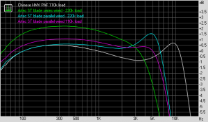
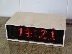
Fig. 1: Some features of these pickups can be seen here – series vs. parallel, the effects of different loading

The Rightmark software is an audio generator/analyzer. It sends test audio to the sound output of the computer, in this case, the output of the Focusrite box (I use the headphone jack on it). When the software is running tests, it monitors and records audio from the input, analyzes it and has the capability of generating graphs of the results.

electronic probe

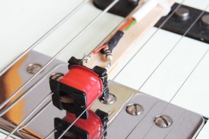
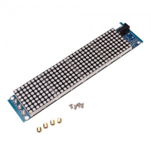
Fig. 2: The probe can be positioned between strings on the guitar if necessary.

The exciter probe consists of a small coil of wire. It was salvaged from a dead flourescent lamp ballast. The coil is wound on a plastic form that was part of an inductor. The ferrite E cores that surrounded it were easily removed. Its DC resistance is about 5 ohms and it measures about 1cm cubed. It is fed through a 100 ohm resistor, in order to provide a current feed, instead of a voltage feed. The ratio of resistance to inductance is high enough that the frequency response is essentially flat from 20Hz to 20KHz. The reason for not using a voltage driven coil of large inductance, is mainly that such a coil, in practice, must have a permeable core which will interact with the device under test and skew the measurements by increasing the inductance slightly. This probe contains no magnetic materials and so should have little effect on the readings. The coil and parts are tie wrapped to a popsicle stick for convenient positioning during tests.

Different resistive/capacitive load networks are used, depending on which tests are being performed. The most basic is a 10:1 resistive divider that functions both as a

schematic

Fig. 3: Basic Measurement Circuit

normal resistive load for the pickup, and as an isolator to prevent the test cable and sound interface input from loading the pickup. For the inductive measurements, a capacitor is placed directly in parallel with the pickup. For the purpose of recording performance curves, it is better to use the integrator circuit because it shows the frequency response more faithfully.

By running a few sweep tests in Rightmark, nearly all of the important information about a pickup can be measured – the resonant frequency, inductance, capacitance, and also the frequency response. I use a spreadsheet to perform the mathematical calculations.

In operation, Rightmark first generates a 1kHz calibration tone at the audio output. At the same time, it measures and displays the input level. The output level is adjustable via the headphone volume control, and the input level can also be adjusted with the input gain control – all on the Focusrite. With some pickups it can be tricky to get adequate signal without distortion (also displayed by Rightmark). After some sweeps, I got warning messages about clipping, but I didn’t see anything crazy in the curves to suggest a major problem. When calibration is complete, you can run a sweep test.

graph

Fig. 4: Results of a raw signal measurement – no integration. The lower curves are with a test capacitor in parallel, used to measure inductance.

Using only the raw signal from the voltage divider with most pickups, the result is a peak with a 6dB per octave slopes on either side. This fits theory perfectly, but requires some explanation about why it is not flat in the pass band. In fact, other researchers data does show a nominally flat signal in the pass band. It is because the probe they are using has a built in 6dB/octave loss due to being a voltage driven inductance. The pickup coil responds according to Faraday’s law of induction, where the output voltage is proportional to the rate of change of the magnetic field. A current driven probe produces a constant amplitude varying magnetic field, since the intensity of the field is proportional to the current. Then the induced voltage in the pickup coil is the derivative of the current, which rises at a 6dB/octave rate (since higher frequency waves have steeper slopes, for the non calculus aware reader).

Parameter Measurement Procedure

Measurement of the pickups two most important parameters, inductance and resonant frequency, are made easily with the Basic Measurement Circuit. First, the pickup is connected to the test circuit, and the exciter coil is positioned next to area of the pickup that is of most interest (in practice it makes little difference). The first step is to measure the inductance. For this, S1 should be closed to insert C1 in parallel with the pickup coil.

Run a sweep with Rightmark. This should generate a peak in the lower part of the audio spectrum, such as the ones in purple and green in Fig. 4. Record the frequency of the peak. Rightmark can be adjusted to narrow down the frequency range so that it is easier to read the exact value, if desired.

The inductance can now be calculated from the equation:

L = 1 / (2*pi*fc)2 / C  , where fc is the capacitively loaded peak frequency

The value of C1 is much higher than the intrinsic capacitance of the pickup itself, and so it “swamps it out” and it can be ignored. Now open S1 to remove C1 from the circuit and run another sweep. This will generate another, much higher peak like the white and blue ones in Fig. 4. The frequency of the peak is just the unloaded resonant frequency of the pickup. Record this parameter.

Now the intrinsic capacitance can be calculated from:

C = 1 / (2*pi*fc)2 / L ,  where fc is the unloaded peak frequency

Equalized Response Curve Graphs

circuit

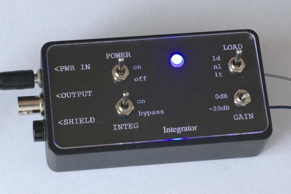
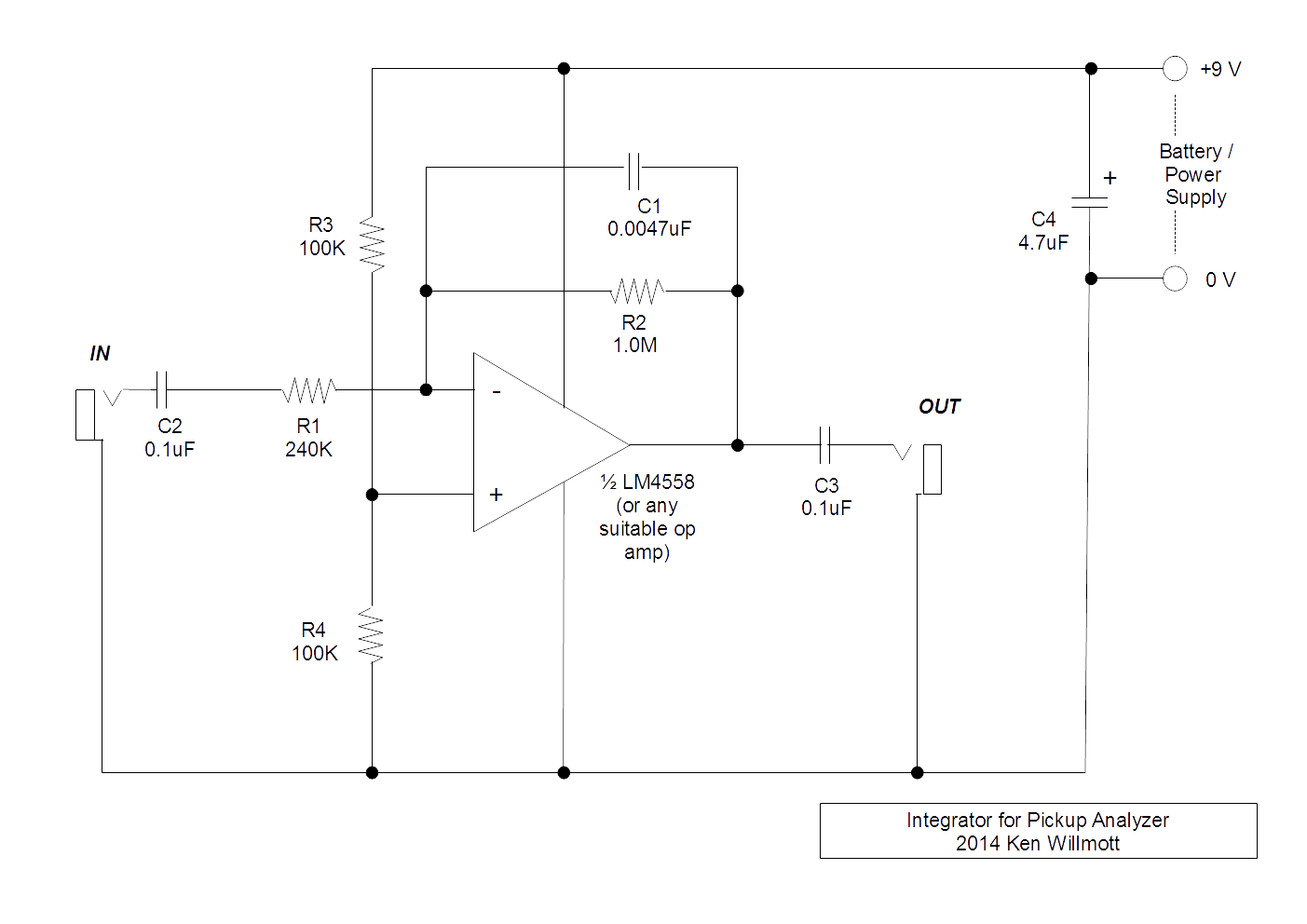
Fig. 5: Original prototype Integrator circuit to equalize for current driven exciter probe

Since there is an overall +6db/octave bias, the flat region in the pass band has a positive slope, and the stop region above the resonant frequency has a -6db/octave slope (since +6-12 = -6). In other words, in the case of a voltage driven probe, the rising slope and the falling slope cancel each other out. Therefore, I built an integrator to place in line between the pickup and the sound card, to eliminate the bias. This has two benefits – it makes the results read more intuitively, and it reduces the dynamic range of the sweep. The non-integrated signal is at the limit when measuring to 12kHz, because the signal gets quite big above that due to the rising slope.

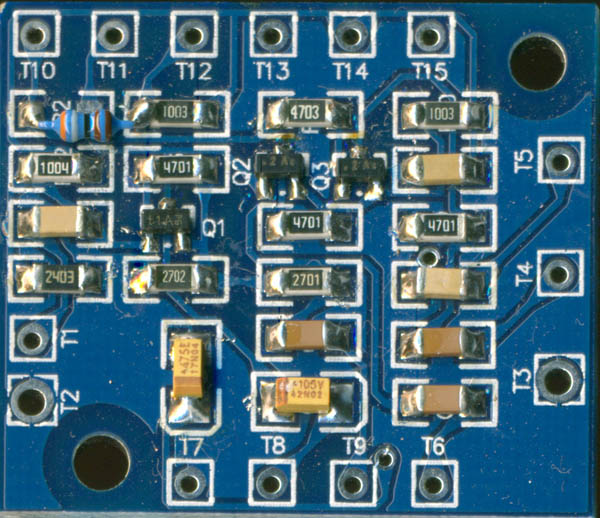
Update 2016/09: I completed the design of a much better integrator circuit. cin_0321
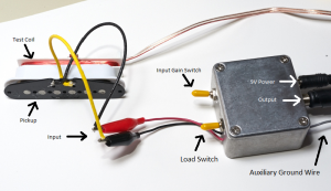
It has already been built and tested by myself and Andrew Flanders, who has been conducting similar research for a few years. It uses a Linear Technologies LT1058 or a Texas Instruments TL084 JFET op amp to achieve a very accurate integration function. It produces much better results than the plot shown in Fig. 6. The input has a built in high impedance preamplifier, which has very low intrinsic capacitance, hence does not interfere with the characteristics of the measured pickup very much. I used Eagle to design the PCB and had it manufactured by PcbWay. You can download the manual here: pickup_measurement_procedure

The electrical model of a pickup coil is well documented, and consists of a large inductance “L” with a distributed internal capacitance “C” and resistance “R”. The internal R determines the Q or “sharpness of resonance” of the tuned circuit of the L and C. However, the internal resistance is not the same as the load resistance, which in practice is the volume potentiometer in the guitar. Powered pickups like the EMG’s use an internal fixed resistor for this purpose.

graph

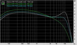
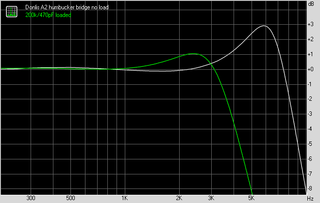
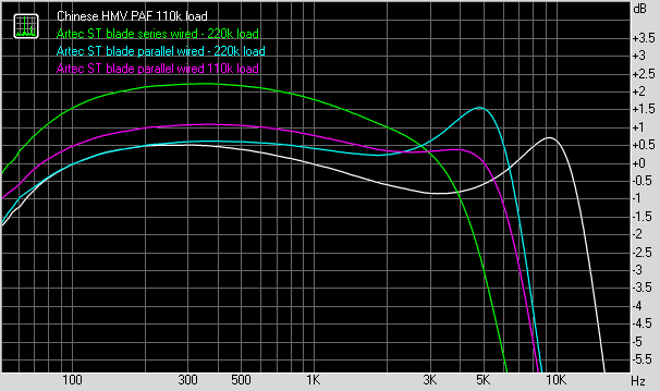
Fig. 6: Here the effect of resistive load is very clear. Notice that this parallel wired pickup has an extremely good high end, but requires a low resistance load to be very flat. The scale is expanded to make small dB differences clear.

The complete circuit includes the pickup and load resistance, and any capacitance that is deliberately or inherently placed in parallel with the load. This circuit has the form of a second order RLC low pass filter, which has a loss above the cutoff frequency of 12 dB/octave. Conveniently, the degree of resonance or “damping” is a well understood phenomenon for this filter, and easy to calculate. This means that the value for the pickup resistive load (usually the volume control) can be tailored to achieve a desired degree of peaking or flatness, without any trial and error. For tests, it is desirable to use a very high resistance because the peaks allow a more accurate measurement of the resonant frequency.

It is tempting, and interesting, to run the tests on pickups while they are installed in the instrument. Although it is not possible to measure inductance and other pickup parameters this way, it can directly reveal a lot of information about the frequency response of the guitar electronics as a whole, including the operation of the tone controls.

circuit layout

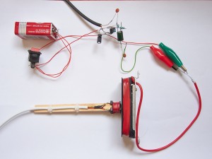
Fig. 7: This is the whole test circuit, looking ugly now because it is built in air! At the top is the battery powered integrator. Magnetic probe is placed on the pickup. It’s a mess because I had no electronic bench in China

The (original) integrator is a standard circuit built around an LM4558 op amp. It allows essentially flat measurements from 100 Hz to 20 kHz. Since it has a -3dB cutoff around 32Hz, the response will show a -6db/octave roll off below that. From over 20 measurements of different pickups in different configurations, I discovered that all of them are flat within a fraction of a dB, below about 200Hz. Therefore, I concluded that it is not worth measuring, and that the 100 Hz value can be taken as a very accurate indication of what it it at, say, 20Hz. It is possible to lower the cutoff frequency of the integrator to include lower frequencies, by changing some resistor values.

This is a prototype and lacks conveniences, however I believe it shows that it is not very difficult to obtain measurements that are useful for installing, evaluating, or designing electric guitar pickups. Next I will explain how to interpret the readings and perform the necessary calculations to derive electrical specifications.

The main effect of a resistive load on a pickup, is to control the peaking at the maximum frequency that the pickup can reproduce. There are two ways to describe the amount of peaking.

One is called “damping factor”, which is sometimes labelled “k”. Values of k greater than one result in a minimum peak, and if much too large, result in a gradual, excessive signal loss at the maximum frequency. Values of k less than one result in a signal peak at the maximum frequency. It produces a strong resonance if k is very small. A typical guitar volume control provides a value of k = 0.5 or less, but I prefer to aim for a more flat response from k = 0.707.

The much more common way to describe peaking, is the Q factor. Q and k are related by the formula:

Q = 1/(2 * k)

Designing a Resistive Load for a Magnetic Pickup

An actual pickup was measured for this procedure. It is a Strat type single coil with steel pole pieces and a ceramic magnet. Instead of using a stock potentiometer and calculating the Q, we can choose a Q that we like, and find the replacement potentiometer value that will produce it.

1. Measure the inductance

The measured DC resistance is 6.2k.

With a 0.1uf cap in parallel with the coil, the measured resonant frequency is 400 Hz. Calculate the inductance:

fc = 1/(2*pi*(LC)0.5)
L = (1/(2*pi* fc))2 / C
L = 1.58 H

2. Now knowing L, we can calculate the coil’s intrinsic capacitance.

The measured self resonance frequency is 8500Hz.

C = (1/(2*pi*fc))2 / L
C = 222 pF

3. Calculate the load resistance to provide a Q of 1.8:

Q = R*(C/L)0.5

R = Q/(C/L)0.5 = 1.8/(222*10-12/1.58)0.5

= 152K ohms

  1. The stock volume potentiometer that was used with this pickup had a resistance of 200K ohms, so the actual value of Q can be computed:

Q = R*(C/L)0.5 = 200,000*(222*10-12/1.58)0.5 = 2.37

Note that these calculations assume that there is no load capacitance, such as a tone control or amplifier cable adds. If the volume control is at the maximum position, the cable capacitance is in parallel with the pickup capacitance and can be added to the calculations. When the volume control is at lower settings, the capacitance is decoupled from the pickup to some extent, and has less influence. The same can be said for the standard tone control, except that we accustomed to call the maximum the “lower” as it is lower in frequency (it has the maximum effect when it is turned down all the way). Changing either the cable or tone capacitance alters both the Q and the resonant frequency.

When the capacitance increases, the Q will increase, and the resonant frequency will decrease. So it is easy to see how a tone control will influence the sound. But if we are interested in the base conditions, it is best to estimate the situation when the tone control is at a maximum (thus mainly out of the circuit), and calculate values including the cable capacitance.

A typical cable capacitance is about 80pF/meter or 25pF/foot. Thus a 3 meter or 10 foot cable will have about 250pF of capacitance. The Strat pickup that we measured above had an intrinsic capacitance of 222 pF. Parallel capacitances add, so the total capacitance is 250pF + 222pF = 472 pF. Since we have almost doubled the capacitance, it will obviously affect the output audibly. Recalculating the Q with cable capacitance:

Q = R*(C/L)0.5 = 200,000*(472*10-12/1.58)0.5 = 3.46

This Q is quite high, but produces the tonal flavour that Strat pickups are well know for. It is not the focus of this section, but worth noting that the resonant frequency has dropped from 8,500 Hz to 5,830 Hz. It is obvious that in order to achieve the desired results, we have to include the cable capacitance in all the load resistor calculations. So, for example, with the Strat pickup, we wanted to achieve a Q of 1.8. Including the cable capacitance:

R = Q/((C+Cc)/L)0.5 = 1.8/((222*10-12+250*10-12)/1.58)0.5

= 105K ohms

An interesting outcome of this analysis is that once the Q for a given resistance, or the resistance for a given Q, are known, different values of Q or resistance are extremely easy to calculate because they are linearly related. A doubling of resistance will produce an exact doubling of Q. So if you are changing your volume potentiometer from 250K ohms to 500K ohms, you can expect an exact doubling of the Q, no matter what it is. In general:

Qnew = Qold * (Rnew / Rold)


RG Kit Guitar

In the quest for the perfect guitar, I thought that exploring some kits would be a cheap way to go. At this point, I’ve already been to many guitar shops and tried out all the most well known guitar models. As I’ve stated before, Telecaster is my favourite. Yet I wondered if there was something I’m missing. So when I saw the “Jason Derulo” kits on the Chinese site tmall.com, I could not resist. I can only confirm by close examination of the photos, but it appears that they are marketed in the west as “Alston” guitars on Amazon.com.

red_guitarI did extensive research online, to try to determine more about the quality, as the merchant description isn’t very detailed. The Amazon product didn’t get good reviews. But I thought I could iron out minor flaws if I got some good wood from it. Unlike some of the other kits, this one has no laminated top or bindings, which some customers complained about the quality of. So, there would be a lesser possibility of flaws. After a few weeks of struggle, I have finally finished the kit. It’s patterned after the Ibanez RG series.

DSCN1769_006I ordered the kit and waited a few days for the EMS shipment to arrive. Everything was carefully packed in a medium sized cardboard box, and a quick inventory revealed that all the parts were included and there was no damage.DSCN1773_005 As I looked it over and began planning, I was optimistic. The two piece neck was straight and the frets were true. It looks like maple, my only complaint is that the wood was not chosen or oriented for the best grain, which should be perpendicular (especially when it is not a multiple lamination). The body consists of three laminated pieces of good quality mahogany. I was extremely grateful for this, as I wanted to use some kind of natural wood finish instead of painting over it. The hardware looked good enough, keeping in mind the price. All the electronics are pre-installed on the pickguard. There are two humbuckers and one single coil pickup, with a 5 way selector switch. More about these later. The pickguard was a botch job. It did not follow the contours of the body well, and the mounting holes for the pickups were off center, enough to be visible from across the room. Also, the pickup openings were oversized. My guess is that they don’t drill each panel individually, they probably take a stack of them and drill through all of them at once. Just a guess. Either that, or they have a broken or no template. So I went back online and ordered a new pickguard from another vendor. Also, I don’t like single coils. So I ordered an Artec strat-sized blade humbucker to replace the middle pickup.

DSCN1782_007I looked around town for wood dye. There is no such thing as a yellow pages here in China. You have to set out on foot and search, or perhaps ask around to find things. Soon I found a friendly store on the main street that sells paint supplies. Although they lacked wood dye in the offbeat colours I had in mind, they had spray cans of automotive lacquer. Well, that’s all they had in spray cans. So I settled for some clear lacquer instead of polyurethane. This would turn out to be a mistake. I went to an art store and couldn’t find anything like a dye there, but I spotted a jar of red ink and realized that it was perfect! I sanded the body and applied a wash of ink after wetting it lightly. After the first coat of lacquer, it looked great.

Next, I considered the electronics. The pickups looked cheap. Well, what do you expect when only one “big name brand” pickup would cost more than the entire guitar? The plastic bobbins are crudely cast, so don’t line up with the base screws accurately. The base legs were bent slightly and the screw holes threaded that way, nonetheless. There was a tiny hint of wax around the outside of the coils and on some of the screws, as if someone had heard about wax potting but didn’t understand what it is for. However, the coils, magnets and pole pieces were adequate to do the job they were designed for.

So I began to hunt for replacements. I narrowed down the search to some EMG-HZ’s that were not too expensive. I also began to research pickups and learned more than I needed to know! After that, I decided I should overhaul the existing pickups to try to improve them, and use the opportunity to test some ideas. I disassembled one with the idea of wax potting it, but the internal connections were made in a way that would make that extremely difficult and risky. Instead, I changed the wiring from series to parallel, and reassembled them, without any potting.

As I lacquered the body, I had a lot of problems. Everything from an outbreak of sea foam like bubbles, to crinkles that appeared in the final finish after an entire week of drying. I did some wet and dry sanding between coats. I think I could make it work next time, with two weeks drying time between coats. I’m not that patient. I never had such problems with polyurethane so I will go back to it for sure.

Examining the neck/body fit, I found two problems. One, the nut was offset, low on one side. I fixed that easily with a shim of sandpaper. Two, the holes for the tremolo bridge posts were 74mm apart. A Floyd Rose or Schaller bridge is almost a millimeter wider, so it will only accomodate a cheaper brand of bridge (many clones on the market are also 74mm). However, the galling fact is that the bridge that they supplied is narrower by yet another millimeter. It doesn’t sound like much, but it means that the tremolo doesn’t pivot properly on the knife edge part of the slot, instead it’s a little off center where it is more rounded. I may gamble on ordering a new bridge, and hope that the new one has the correct 74mm spacing. I used a pencil to apply graphite in the area for lubrication when the guitar was finished. However, I can see now that it does affect the ability of the tremolo arm to swing back into rest position properly. This small detail makes a huge difference in the end! At least I don’t have to modify the body.

A strange thing, no doubt, is the “2-4” arrangement of tuners on the headstock. I did that to shorten the neck so it would fit in my suitcase when I return from China! I chopped off 6.5cm. and drilled two extra holes for the E and B tuners.

guitarThe Artec pickup and replacement pickguard arrived on the weekend, so it was time for final assembly and test. There was a lot of time spent in setting up the tremolo springs, the string height and the intonation. Many long hours, but it came together at last. What are my feelings about it as a player? I like the thin neck and wide fingerboard, but I don’t really care for the jumbo frets. One plus, the frets were already aligned well enough that they didn’t need to be dressed and crowned. Of course it is a good idea, but it’s optional in this case. I was able to adjust the action down very low without any buzzing. I don’t like the “tummy tuck” cutout in the upper body. It makes the upper body press into my chest as I play sitting down. The volume control is too close to the strings, my fingers keep hitting it. It might be true for any tremolo system, but tuning is a huge hassle. I broke a string right away, and it’s amazing I didn’t break more. You see, when you tune any string down, all the others go up! Also if you use the lock screws on the nut and forget about it and turn the machines, you will surely break a string there.

The sound is great. The parallel wiring does seem to give a clearer sound. As an experiment, to compensate for the lower impedance, I put a 100k ohm fixed resistor in parallel with the volume control. It should help damp the pickups natural self resonance, which might otherwise sound a bit edgy. An interesting phenomenon, is that playing with the middle pickup alone sounds really good. I didn’t expect that. I swapped the neck and middle pickup connections on the selector switch. This allows me to select bridge and neck pickups together, while sacrificing the ability to select bridge and middle together.

Here is the cost breakdown, in Chinese yuan:

  • guitar kit – 480
  • pickguard – 16
  • Artec pickup – 60
  • Spray lacquer – 30
  • Red Ink – 8
  • Shipping – 65

So, the total cost was 659 yuan, or approximately US $105. If I replace the bridge, It will come to  US $120.

Bacchus Telecaster gets new pickups

I brought GFS pickups to China to install in the Bacchus Tele, TC70 True-Coil noise cancelling Stratocaster type neck pickup, and the H102 Lil Puncher XL Modern Vintage Tele bridge replacement. I had already installed a Seymour Duncan JB humbucking pickup in the middle position.
bacchus000
At the same time, I replaced all the tuners and chrome screws. Since there were three pickups, I also brought a 5-way selector switch to replace the original 3-way. I already implemented a custom selection scheme on my American Standard Tele. I liked it so much, I decided to use it again. Basically, it allows you to use some extra selections that aren’t normally available with a 5-way switch. You can hard wire it, as I did, or make it selectable with an additional SPST switch. Here is the schematic:
3_way_pickup_wiring PDF drawing

The selector works as a 5-way normally does, with two exceptions. Normally, position 1,3, and 5 select bridge, middle and neck pickup individually, and the “in between” positions 2 and 4 select bridge/middle and middle/neck respectively. With my modification, position 4 gives you all three pickups, and position 5 gives you neck and bridge.

I have several reasons for doing this. For one, I happen to like the sound of the neck+bridge combination, and I refuse to give it up. The only time I play with the neck pickup only, is on my homemade Tele with a mini-humbucking in that position. Not on this guitar. When I installed and tested everything this time, I didn’t get as much tonal difference as I expected. So I reversed the phase of the middle pickup. It give me phase reversal in two positions, while preserving normal phase in the other three. So, I don’t have to have a raft of switches cluttering the front of my guitar (I don’t have the tools to mess with it now, anyway).

Here is the rundown on this dandy arrangement:

Position 1 – Bridge pickup, classic chicken picken country twang.

Position 2 – Bridge/Middle out of phase. Weird spacey hollow sound.

Position 3 – Middle pickup. Brassy, straightforward sound. Usually a little sharp sounding.

Position 4 – All pickups, Middle out of phase. This one is complicated. The neck/bridge combination is in phase, so it predominates. The middle out of phase tends to just knock out the lows a lot.

Position 5 – Neck and Bridge, together and in phase.

I’m quite happy with the result. I had a custom pickguard made to accommodate the Strat neck pickup, which is much larger than a Tele neck pickup. Alas, the Bacchus body has randomly different dimensions (probably to avoid Fender copyright infringement) and it didn’t fit. I pondered my dilemma and eventually realized that the Strat pickup would just barely squeeze into position on the original pickguard, if I removed the white plastic cover. So that is what I did. Time will tell whether the bobbin is strong enough to be exposed like this, I am not too worried about it because it sits quite low and is securely mounted.

Differential Distortion Revisited

Differential Distortion PCBI designed a guitar distortion device in 1995. It was published in Popular Electronics magazine, August 1995 issue. I dubbed it “Differential Distortion”. With the advent of the web, the circuit was copied and added to many online compendiums of guitar circuits. I was very happy to see that, because I thought some people might benefit from some important features of the unit. Mainly, the extremely low battery drain, which might make it more practical to build into a guitar if desired. It’s also quite small, with a low component count.

Sometime around 2005, I had access to a full SMD workstation, and drawers of SMD resistors and capacitors. So the bug bit me again, and I decided to build the circuit using SMD parts. I ordered the transistors online, and had the boards made by a small run OEM manufacturer. The parts were insanely small – 0402 resistors look like grains of pepper in a jar. But I had a stereo microscope to help. I built a few of them, tested them. Then a big house move hit me, and the project languished in boxes for a few years.

In 2013, I went to an electronics mall called Chenghuangmiao in Chengdu, in the province of Sichuan in China. I have never seen so much electronics in all my life. It struck me that, not only there, but everywhere now, SMD parts have taken over from the old through-hole components. The new stuff is smaller, cheaper, and often has tighter tolerances. As I left the mall, I looked in a doorway and saw someone doing CAD layout. Looking around the store, I realized that they could build prototype boards. So it was back to the drawing board again.

I consulted my old plans, and went back to shop. But the low noise 2N5088 transistors were nowhere to be found. I realized that I would have to substitute another part. The sellers there are basically merchants, only a few have any deep engineering knowledge. So my attempts to explain my need for a “low noise” transistor were futile. One store assured me that, “all our transistors are low noise”, I think they believed I was impugning the quality of their wares. So I simply copied their lists of available parts, and went home to use the internet to look at data sheets. This led me to choose the excellent and common MMBT9014/MMBT9015 NPN/PNP types.

At the same time, I started reading opinions and experiences with the circuit that were posted on various forums. I realized that I had a few improvements of my own in mind. So a complete redesign was undertaken, with an eye to retaining all the worthy features. It has to be said, that the role for an analog device like this has been sidelined by digital audio and DSP emulation in the commercial market. Also, that as a consequence, nostalgia has led DIY builders in the direction of re-creating older designs, rather than looking in new directions. Still, some people had built it, and even reported the results of some modifications that they had dreamed up. Some implementations I didn’t agree with, but there were some good ideas to work with.

First, I made some important engineering changes. The single resistor emitter bias in the input transistor circuit of the original, was too unstable and sensitive to component and battery voltage changes. So I fixed that with an extra capacitor and resistor in the emitter circuit to lower the DC gain. The audio output level was too low, so I increased it. The input impedance was too small, so I increased it as much as I could. The 0402 parts were too small, so I used 1206’s. There is an advantage that the resistor values are readable. Next generation, I think I can step down to 0804’s and still be able to hand assemble with only soldering iron and tweezers.

Next I accomodated the mods. I added an inverting output to the differential pair. This allowed a kind of “distortion depth” control to be added. Or call it “fuzziness”, “bite”, “grunge” if you like. I also added a bias control circuit that allows the differential offset to be varied to change the harmonic tone and sustain. Some people thought the sound was too harsh, so I added an optional low pass filter on the output. The classic Fuzz Face that is a classic fuzz design, had an extremely low input impedance (stupidly low!). When guitar pickups are loaded this way, it cuts out the highs. However, the sources I was using claimed that it cut out the lows, so I added an adjustable high pass filter on the input to emulate that. It was implemented after the board design, so it is the only off board component option. That means that the area of input filtering needs a lot more experimentation.

At every step, I wrestled with the design goal of simplicity, with a lot of bang for every buck. So I didn’t allow myself to get too fancy. Most of all, I didn’t want to use any more battery current. Since I was mass producing one board, I tried to make it possible to change options just by changing the external wiring. For example, it can have the variable controls, or fixed settings, using only some jumper wires.

The board was laid out from a schematic and some sketches in about an hour, by a diffident but efficient young man, who was terribly late and had to be coaxed in by phone by the management. He did a good job, but didn’t fully understand my request to lay out thermal breaks on all the pads. With wave or oven soldering, the entire board is heated, so small components can have leads soldered to large areas of conductor. If you are hand soldering or doing repairs, this creates a nightmare as the conductor sucks up all the heat from the iron and refuses to get hot enough to make a proper joint. Or sometimes, the extra heat damages things. He did follow the instructions on ground connections, but didn’t realize that I wanted it on every connection. So a few of the components on the board were really pesky to place. I will be really demanding on this issue next time.

My order of 200 boards was completed in about a week. I found one mistake, my fault because I left the schematic at home and had to draw them the circuit from memory. I figured out that I could fix it with one 1/16 watt resistor, you can see it placed as a jumper on the top left of the board. Some boards had defects, but they had done a full inspection and marked them out. They even placed parts on two of them for me! The price was very reasonable, of course. It’s China. I remarked to my Chinese friend, that in my country a PCB company would look down their noses at me for even daring to ask to have such a job done. There are some mail order houses, but they are very pricey for a full build – mask, screen and assembly. There was no extra charge for the layout work!

I built about 80 boards. I don’t have them where I am now, but I plan to make some available as DIY kits. Originally, I thought I would supply the board and components separately, but as I mentioned, the SMD assembly is too difficult. I could do it next time with the board improvements. The circuit is simple enough that it can actually be built up on perfboard or whatever you like, as you like. I want to build a version that has the potentiometers and switches all on board, so it is a complete module that requires only battery and audio connections. The idea is to drill holes in the pickguard so it can sit in the control cavity of a guitar.

The first schematic I have posted is a shop drawing, so there are some things I need to tell you. The board is about 2.0 x 2.5 centimeters. The input is on the left, output on the right. The two potentiometers VR1 and VR2 are 10k linears. Switch S3 chooses clean or fuzz, S4 is the output low pass, S2 is the input high pass. You can substitute a 250k potentiometer for S2 if you want it variable. To eliminate the bias control, jumper T10 to T11. To eliminate the fuzz control, jumper T8 to either T6 or T7, whichever sound you prefer. To eliminate S3, just use T4 as the final output (T4-T5 jumper is not required). The dot marks on the potentiometers indicate the fully clockwise position – all the way to eleven as Spinal Tap says! 🙂

The second schematic shows the circuit design better. If you are interested in how the circuit works, or want to build your own, this is the one to study.

As a stomp box, it is possible to have the battery switched on from the jack, so it is automatically on whenever it’s in use. I didn’t show that, because it’s not how I do it. But it is possible. The people that copied my circuit included it in their version. Go have a look.

Here is the shop drawing, showing the off board wiring:
Differential_Distortion_Schematic
Here is the general schematic:
differential_distortion_general
Here is the original 1995 schematic:
diffuzz.gif