V6.0 Integrator is released
The production case is ready. The old V5.8 circuit has been adapted for automated SMD PCB production, and there are a few changes.
- the operational amplifier has been upgraded to a faster component, which increases high frequency accuracy
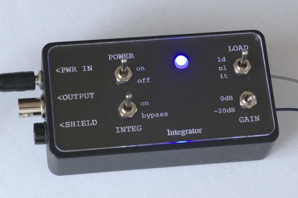
- the non-integrated output is no longer switch selectable, instead it is routed to the ring connector on the 3.5mm stereo output jack
- the test leads are now screw terminals which allows for easy replacement or customization
- the SMD components have more accurate tolerances than the through hole ones on the V5.8
- all switches and connectors are mounted on the PCB, which simplifies the assembly and allows it to be used stand alone, with the acrylic case, or with the aluminum case


Attention! Please Read!
If you are interested in purchasing integrators or integrator components, you can leave me a message via the contact page. However, I have recently found that some of my replies are being rejected by spam filters. So if you have left me a message, you can generally expect a reply within 24 hours. If you do not, it is likely that my reply has been blocked and you should please have a look in your junk or spam filtered folder in your email client. I use email because it suits my international, niche market and e-commerce tools are too limited or expensive for my sales. Unfortunately, email has become a kind of wild west with no real guarantees of smooth delivery but it is still the best way for me.
Also because of the limited market, it is not economical or feasible for me to set up an online store where you can simply shop and check out your purchases. The global distribution of my customers also means that optimum shipping varies considerably depending on which country I’m sending to. Consequently, I operate by communicating with each individual customer via email, to choose the right kit or parts and to choose the best payment and shipping options.
U.S.A Customers
The de minimus exemption of duties on items entering the United States was eliminated by an order of its president. This would mean that American customers would pay a surcharge on my product. The Canadian post office now requires a third party agent to collect duty charges before shipment, therefore I would be involved. I will no longer ship my products to the United States until reasonable political and economic policies are re-instated. Instead, I created a bulk order link, so it will be possible to order quantities of 5 or more integrator PCBs directly from the factory in China.
The design pattern for the acrylic case can be found at the Github site, and the metal case is a common case that can be ordered from online vendors (but you have to drill your own holes).
https://www.pcbway.com/project/shareproject/W22492BSH46_integrator_V6_Gerber_e358a0f5.html
Once there, you will see an order link to the right:

Click on “PCB+Assembly” and “Add to cart”, you will then go to the order screen. It has been pre-filled with default data which you do not need to modify unless you wish to change global parameters like quantity of boards. It looks like this:

When you press “Submit” it will make an order for you. The assembled cost is more than the boards alone. So, you will have to wait while the engineering team sources the parts and gives you a final quote. That may take as long as several weeks, so please be patient. Be aware that since you have ordered the PCB’s to be manufactured, you will have to pay for those even if you later decline the assembly cost (unless you make special arrangements with PCBWay).
How to order
In order to simplify the shipping arrangements, please send me an email with the details of your request via the contact form on this page or reply to any of my previous emails. Include any questions, and your complete postal address. If you do not live in Canada, also provide your contact phone number because it is required for the customs forms. Shipping will be by tracked parcel post, and is paid by the client (you). I accept payment via Paypal. Again, it is not practical for me to ship to the USA. I have no control over this development.
Price List:
- Complete unit (in aluminum case): USD$135 only one unit left
- Complete unit (in acrylic case): USD$68
- PCB assembled with parts (switch and on board connectors): USD$45
Open Source Hardware
This product is completely open source, using the MIT license. Want to build, modify, or sell it? No problem. Or maybe you just want to know how it works, in detail. Here you go:
https://github.com/KenWillmott/integrator-v6
please follow the links to the older V5.8 repository, the main Wiki is also there
User “GuitarMD” has made an excellent video covering usage of the integrator. The only difference when using the V6.0 will be in the type of connecting cables used.
It is possible to order quantities of the assembled PCB directly from the factory:
https://www.pcbway.com/project/shareproject/W22492BSH46_integrator_V6_Gerber_e358a0f5.html
About the previous integrator
The V5.9 Integrator is no longer available. The very last few bare PCB’s and PCB’s assembled with switches are now sold out. Also, I decided to remove the factory order link for the V5.9 PCB and optional assembly. This is because it was meant to be a temporary measure while the new integrator was being designed.
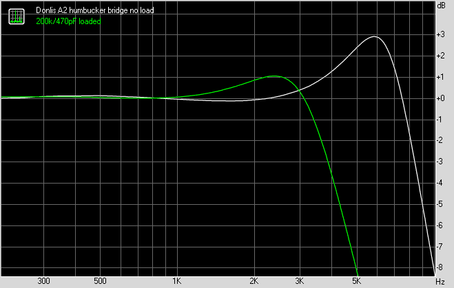
This device contains a high impedance pre-amplifier and signal integration function, for analyzing electric guitar pickups. It has gone through several stages of prototyping and design improvement. The latest update is an acrylic front panel. It looks really cool in the dark, although you probably won’t be testing pickups in the dark!

As a specialized test instrument, the market for it is relatively small, so a challenge was met to offer a product that is both economical and robustly constructed, and also can be made by an experimenter, following the free and completely open online documentation and design files, found here:
https://github.com/KenWillmott/integrator/wiki
In the spirit of open source, I made it possible for any customer to choose whether they wish to make their own, or purchase component parts or complete units from me. I offered a variety of kit options, from only the PCB, to a parts kit and assembled PCB, all the way to assembled, tested and calibrated unit.
Many people have already purchased and/or built some previous version of the Integrator. Any of those do work perfectly well, but if any previous customer wishes to upgrade to the new product, please contact me with the details of the their unit, for an assessment of upgrade options.